
SCALES
Each offers a size for your needs or space availability
to develop the hobby, the most popular scales are "HO" and "N"
because you can develop in a short space lying at a reasonable price.
In the photo at right shows an example of five scales, beginning
from above we have:
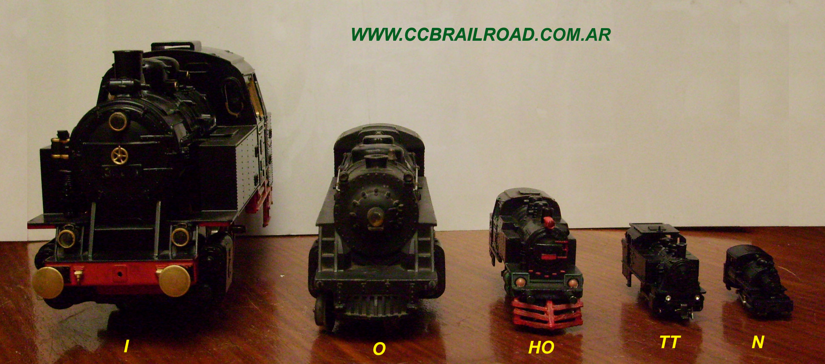
I = 1:32 O = 1:43 HO = 1:87 TT = 1:120 N = 1:160
scales such as the "O" or the "1" are perfect to be able to develop
Outdoor hobby, ie you can assemble cables in the garden of your home.
As you can see several scales
from which you have:
NAME
|
SCALES
|
TRACK
|
1 meter
at
|
Z
N
TT
HOn3
HOm
HO
S
O
I
|
1:220
1:160
1:120
1:87
1:87
1:87
1:64
1:43
1:32
|
6.5mm
9mm
12mm
10.5mm
12mm
16.5mm
22mm
32mm
45mm
|
4.5mm
6.25mm
8.33mm
11.48mm
11.48mm
11.48mm
15.62mm
20.83mm
31.25mm
|
In terms of dimensions (in mm) of BALLAST
with actual measurements from 8 to 12 cms. long
and 4 to 8 inches thick / wide stone
have in the main scales:
NAME
|
SCALES
|
Length
|
Width
|
Thickness
|
Z
N
HO
O
|
1:220
1:160
1:87
1:43
|
0,3 a 0,5
0,5 a 0,7
0,9 a 1
1,7 a 2
|
0,2 a 0,3
0,3 a 0,4
0,4 a 0,5
0,8 a 1,7
|
0,2 a 0,3
0,3 a 0,4
0,4 a 0,5
0,8 a 1,7
|
The table below gives the percentages of
extension (red)-reduction (blue) of the original plans
among the four most common scales.
| |
N |
HO |
S |
O |
| N |
0 |
183.7 |
250 |
333.3 |
| HO |
54.4 |
0 |
136.1 |
181.4 |
| S |
40 |
73.5 |
0 |
133.3 |
| O |
30 |
55.1 |
75 |
0 |
Value of times in the Railways
Epoca
|
Years
|
I
II
III
IV
V
|
Until 1920
From 1920 to 1945
From 1945 to 1970
From 1970 to 1985
From 1985 to present
|
List of steam locomotives shafts.
Ro
notation
American
|
Ro
notation
English
|
Name
|
Switchers
|
0-4-0
0-6-0
0-8-0
|
0-2-0
0-3-0
0-4-0
|
|
Old-Timers
|
4-4-0
4-6-0
|
2-2-0
2-3-0
|
American
Ten-Wheeler
|
Carga
|
2-6-0
2-8-0
2-8-2
2-8-4
2-10-0
|
1-3-0
1-4-0
1-4-1
1-4-2
1-5-0
|
Mogul
Consolidation
Mikado
Berkshire
Decapod
|
Passengers
|
4-4-2
4-6-2
4-6-4
4-8-4
|
2-2-1
2-3-1
2-3-2
2-4-2
|
Atlantic
Pasific
Hudson
Northern
|
Articulated
|
2-8-8-2
4-6-6-4
4-8-8-4
|
1-4-4-1
2-3-3-2
2-4-4-2
|
challenger
Big Boy
|
Value Identification Diesel Locomotives
Notation
|
Details
|
*** Electo Motive Division ***
General Motors
|
SW
|
Switcher locomotive construction
SW 1936-74 to SW1500
|
F
|
Streamline Locomotive loading
FT 1939-60 to F9
Class B, 4-axis
|
E
|
Streamline Passenger Locomotive
EA 1938-63 to E9
Class C, 6-axis
|
GP
|
General purpose locomotive
(Normal load)
GP60 GP7 1949-92 to
Class B, 4-axis
|
SD
|
Special Pesos locomotives
(Normal load)
1952-92 SD7 to SD60
Class C, 6-axis
|
*** General Electric 1930 to 1992 ***
|
U
|
Universal Locomotive
1959-75, U23 to U36
4-axle class B - Class C 6-axis
|
C
|
Class C, 6-axis
1976-88, C30 to C39-7
|
B
|
Class B, 4-axis
1977-88, B23-7 to B39-8
|
Dash 8-40
|
Clase B, 4 ejes
Clase C, 6 ejes
1988-94
|
Alco 1929-1969
|
S
|
Switcher locomotive
1946-69
S-1 to S-13
|
RS
|
Road Switcher Locomotive
1941-67
RS-1 to RS-36
|
FA
|
Cargo locomotive Aerodynamics
1946-56 FA-1 through AF-2
Class B, 4-axis
|
PA
|
Passenger Locomotive Aerodynamics
1946-53 PA-1 to PA-2
Class C, 6-axis
|
C
|
Cargo Century Series Locomotive
1963-69 C-420 to C636
|
Relationship between the scales and the trails of each
NAME
|
SCALE
|
TRACK
|
Possible scales approximate
|
Z
N
TT
HO
S
O
I
|
1:220
1:160
1:120
1:87
1:64
1:43
1:32
|
6.5mm
9mm
12mm
16.5mm
22mm
32mm
45mm
|
1:160(Nm) - 1:120(TTe) - 1:87(HOi)
1:120 (TTm) - 1:87(HOe) - 1:64(Si)
1:87 (HOm) - 1:64(Se) - 1:45 (Oi)
1:64(Sm) - 1:45(Oe) - 1:32(Ii)
1:45(Om) - 1:32(Ie)
1:32(Im)
|
WEIGHT OF ROLLING STOCK
Freight Cars
To calculate the freight cars using the following formula: a basic weight of 30 grams. and adds 15grs. for each 25mm long
| LENGTH (feet) |
PROTOTYPE |
HO LENGTH (MM) |
WEIGHT Grs. |
| 24 |
Miners |
89 |
85 |
| 36 |
Tanks and Hoopers |
127 |
106 |
| 40 |
Steam load time |
140 |
114 |
| 50 |
Standard length 1950 |
178 |
136 |
| 60 |
Modern flats |
216 |
160 |
| 85 |
Beaches |
305 |
215 |
PASSENGER CARS
To calculate passenger cars using the following formula: a basic weight of 50 grams. and adds 15grs. for each 25mm long
| LENGTH (feet) |
PROTOTYPE |
HO LENGTH (MM) |
WEIGHT Grs. |
| 30 |
Short Service |
105 |
115 |
| 36 |
First time |
127 |
126 |
| 40 |
Early 1900 |
140 |
134 |
| 48 |
First Harriman (wood) |
167 |
150 |
| 50 |
Standard since 1930 |
178 |
157 |
| 60 |
Standard since 1950 |
216 |
180 |
| 65 |
Metal with rivets |
226 |
186 |
| 75 |
Straline |
260 |
206 |
| 85 |
Supercine |
295 |
230 |
For locomotives the calculation is made on the basis of 250grs. but the addition of 25 grams. per 25 mm. It is clear that the final weight can vary by model and time of construction.
The weight should be evenly distributed throughout the machine in the case of diesel or electric, in the case of steamers weight should be concentrated on the section containing the tractive (boiler or tender) in a ratio of 65% ( power) to 35% (Dumi) as.
WIRE LOCATION CATENARY
The following table gives the minimum and maximum heights from the rail head for the placement of the catenary wires in each of the scales.
NAME
|
SCALE
|
ALTURA
CATENARY
MINIMUM
|
ALTURA
CATENARY
MAXIMA
|
Z
N
TT
HO
S
O
I
|
1:220
1:160
1:120
1:87
1:64
1:43
1:32
|
26 mm
35 mm
45.5 mm
62 mm
82.5 mm
114 mm
157 mm
|
30 mm
40 mm
52.5 mm
73 mm
98.5 mm
139 mm
194 mm
|
LOCATION OF POLES OF WAY CURVE catenary
The following table shows the distance between vias catenary poles of different radius.
Radio
curve
Employee
|
Distance
between
poles
|
79 cm
65 cm
55 cm
47 cm
42 cm
36 cm
|
24.8 cm
20.4 cm
17.2 cm
14.7 cm
13.2 cm
11.3 cm
|