SOLVING LINKS
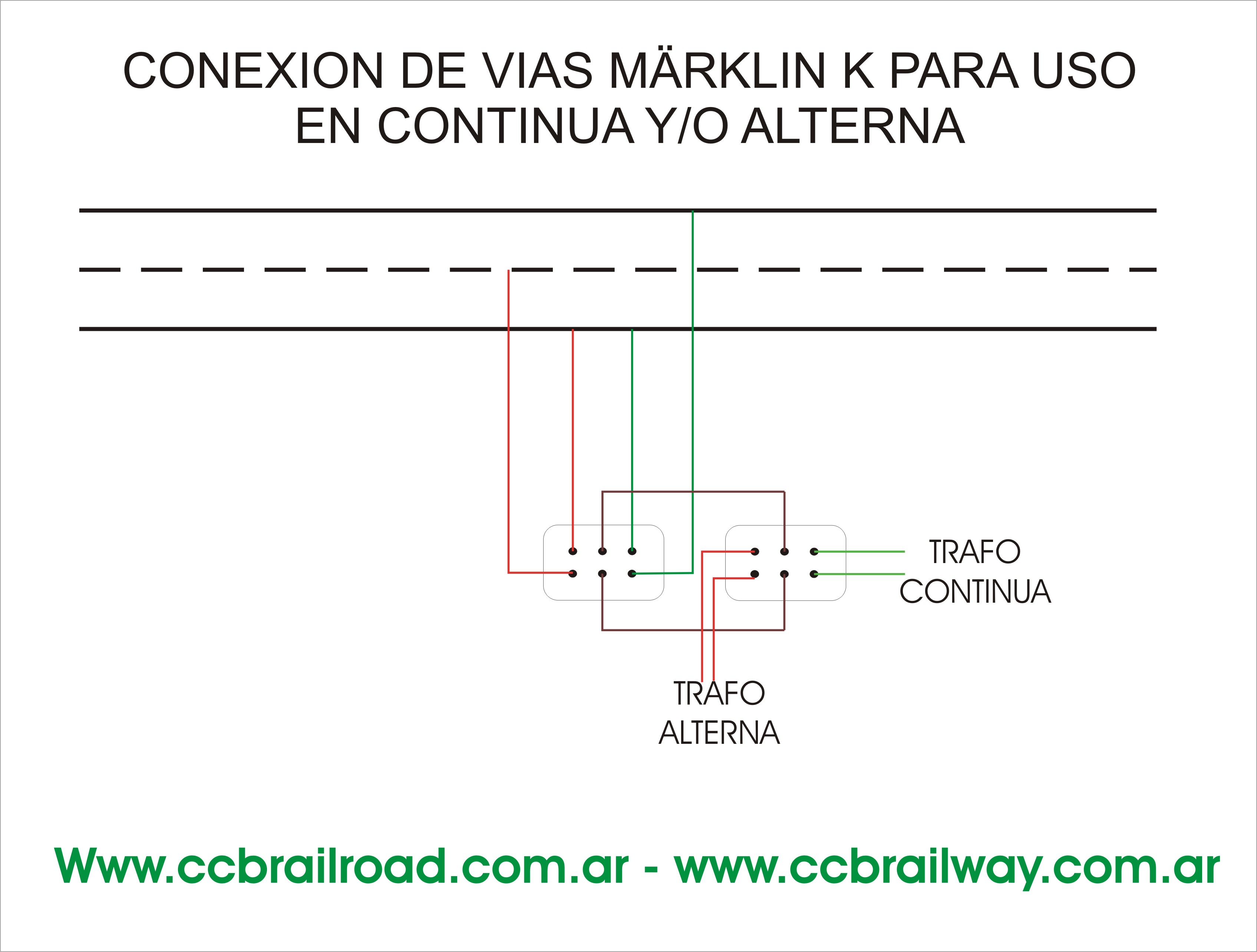
How to connect one-way Märklin C for use with direct or alternating current, taking into account that must be made for each section or canton if you use multiple formations
both systems separated by insulating fishplates external Rails.
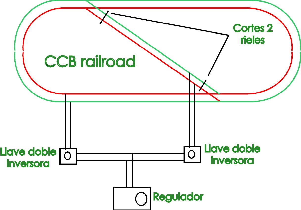
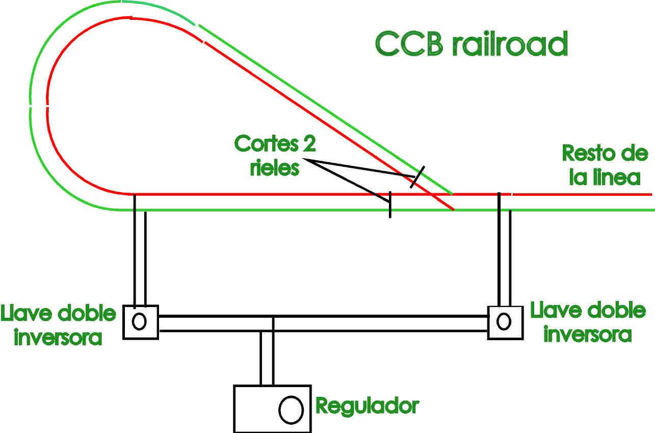
One of the most common problems in DC power lines
is that if you want to do a loop that returns on the same route or a
oval cross from side to side as we diagonal produces a short
circuit due to reconnect cross rails, but the solution
is the addition of a couple of cuts and a couple of key investors with
which solves the problem.
The diagrams below show the wiring of each:
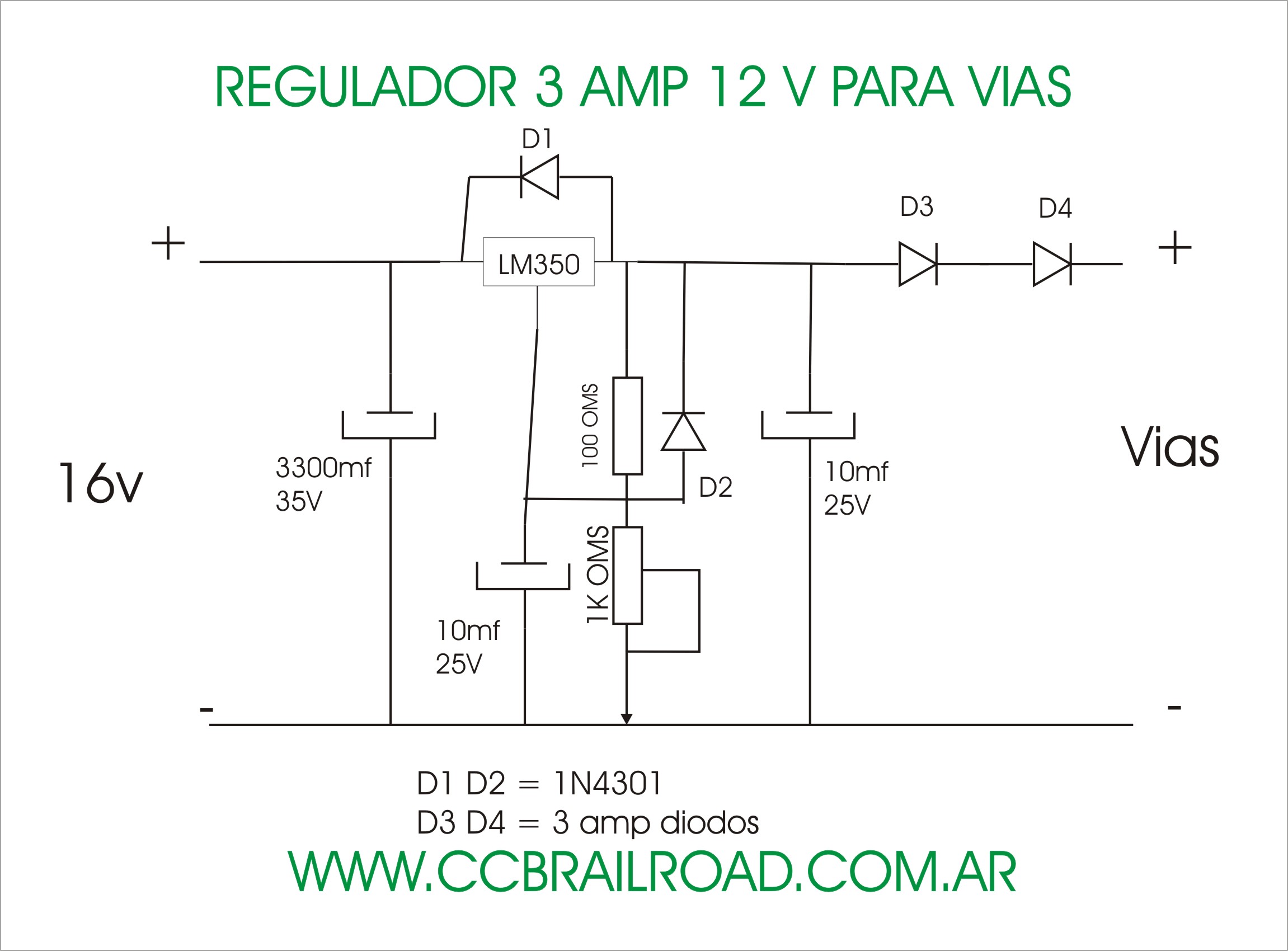
In this scheme is shown assembling a regulated from 0 to 12 Volt 3 amp. The entrance is from 16 Volts DC 3 amp. the components are common.
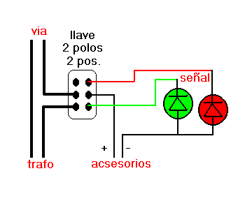
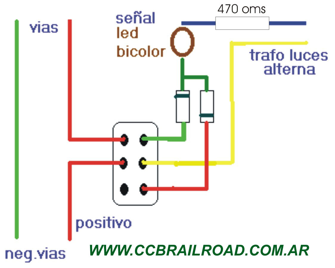
Another issue is to connect signals while performing cutting
via the stream to catch red light, a simple solution is to
a double key investor, this circuit serves for both AC and
continuous, as is shown in the diagram below:
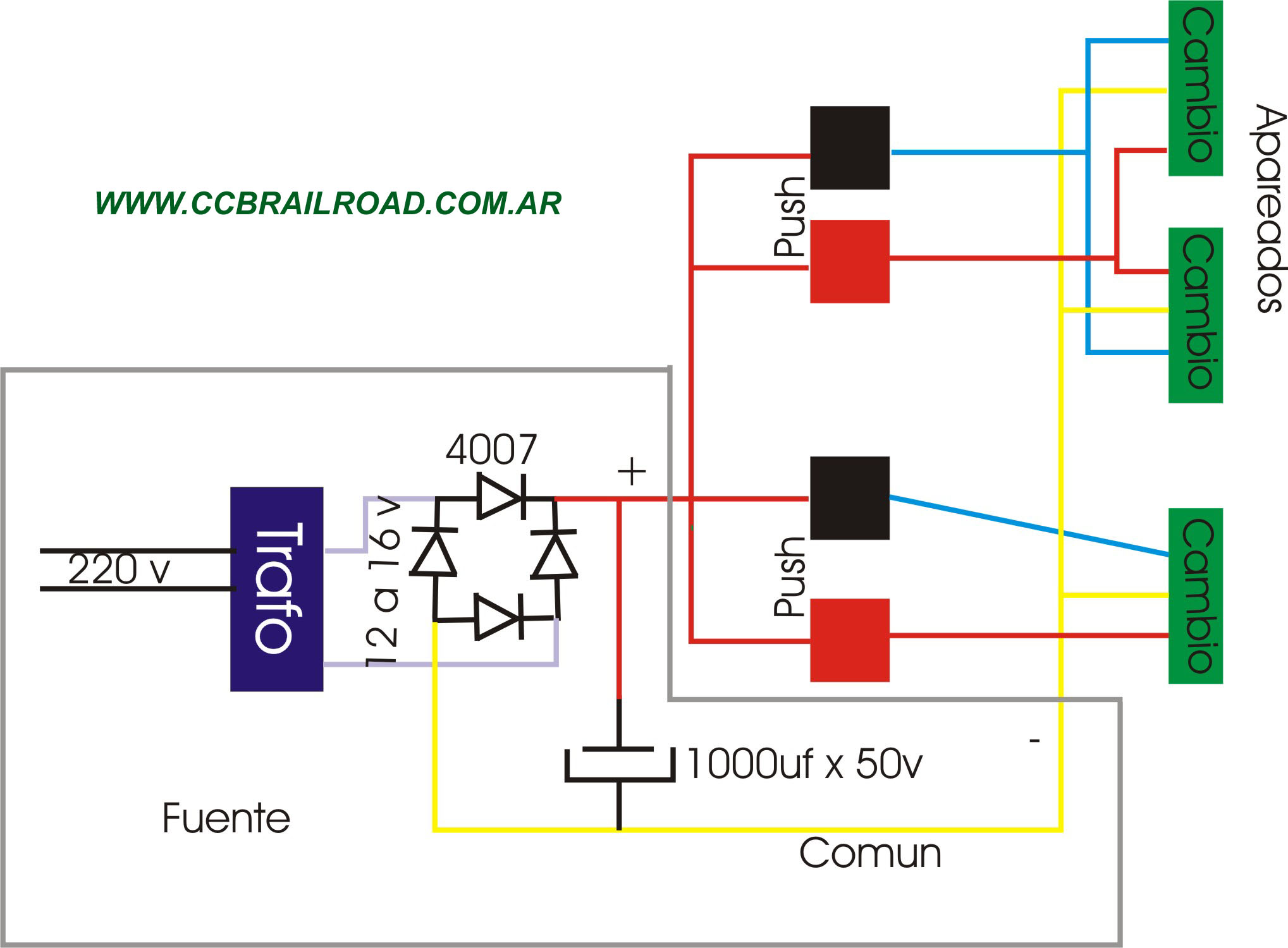
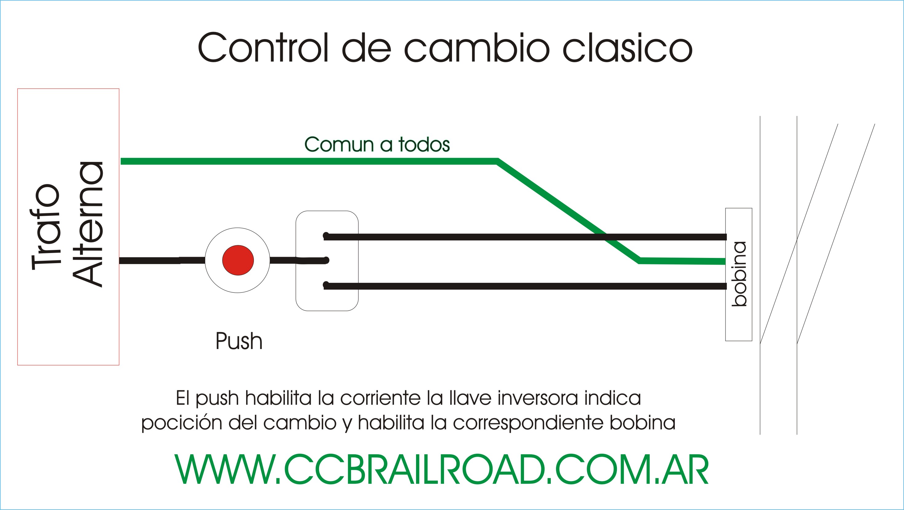
Another issue is the connect changes or needles to control them remotely started with a CT
independent for them exclusively,
a bridge rectifier for DC power and an electrolytic capacitor to energize them
We will use two pus for each change and in the case of the paired 2, 3, or 4 changes will use two push for all,
the Center wire of the changes is common to all and is connected to the negative of the source, the other two pass
one for each push and connected to the positive supply
such which is shown in the following diagram:
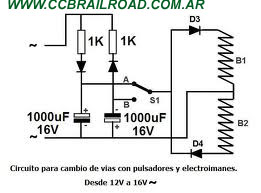
The following diagram shows how to do the same as before but with a simple key and bright indications of Board position.
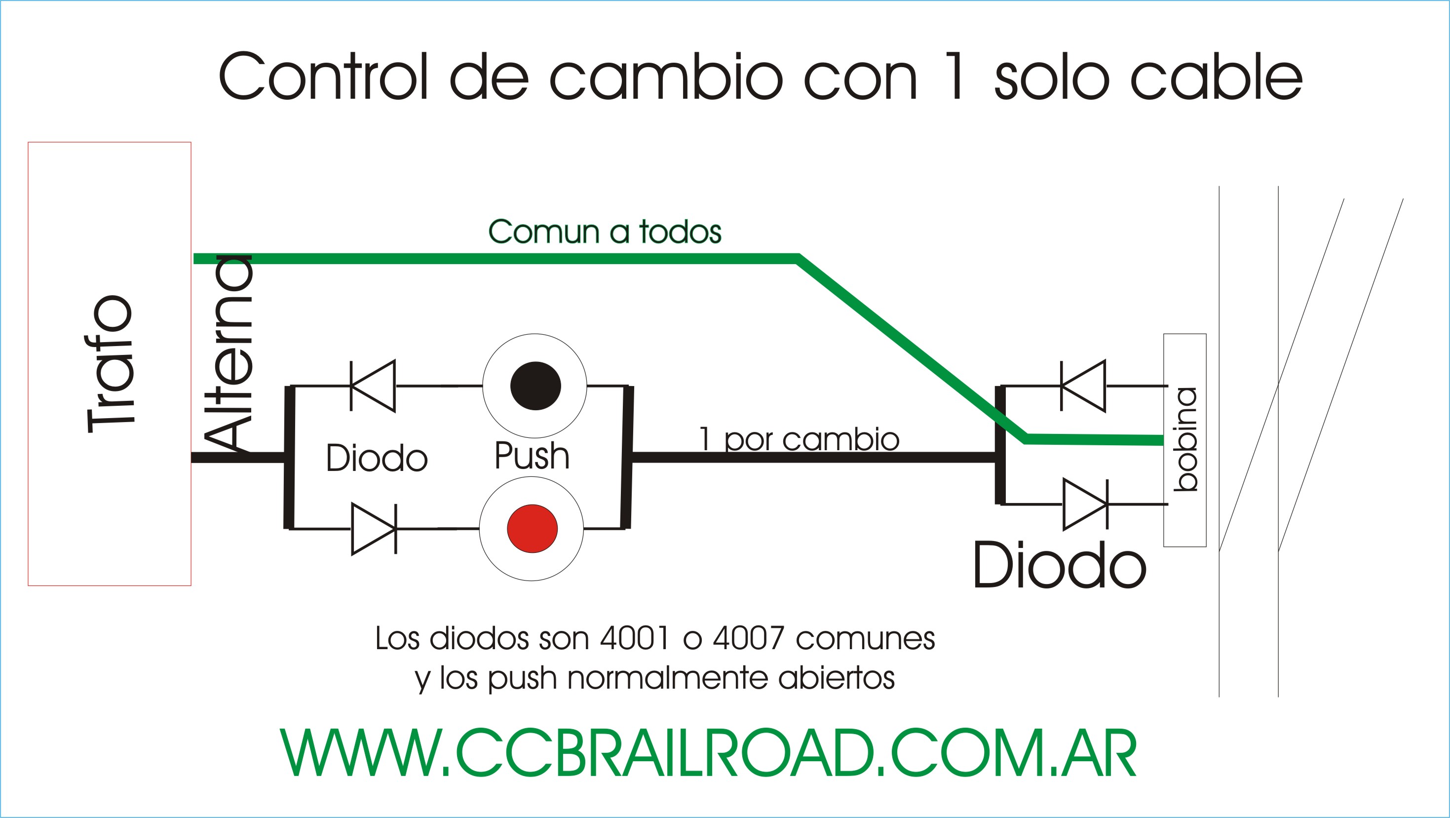
The following diagram shows how to do the same but using a single cable actuated by change and one common to all with the use of diodes 4001-4007.
The following diagram shows how to do the same thing but with a key and a push for change and one common to all.
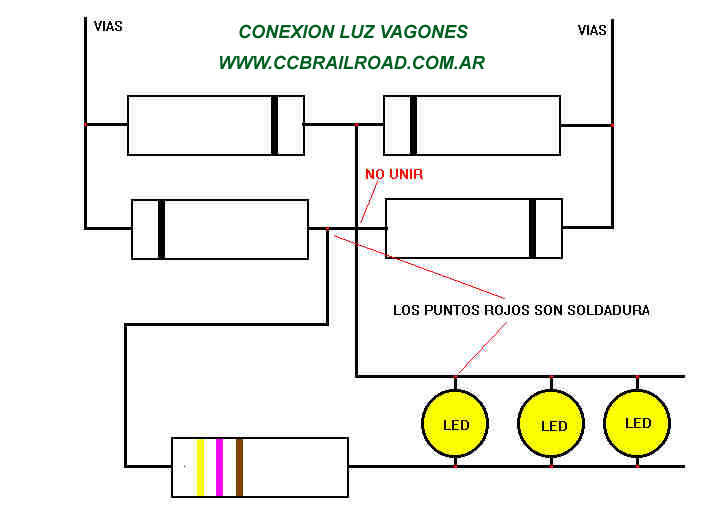
In this scheme is shown as light passenger cars either for AC or DC regardless of the direction of movement.Resistance may vary between 470 and 1200 ohms, any line 4001-4007 diodes.
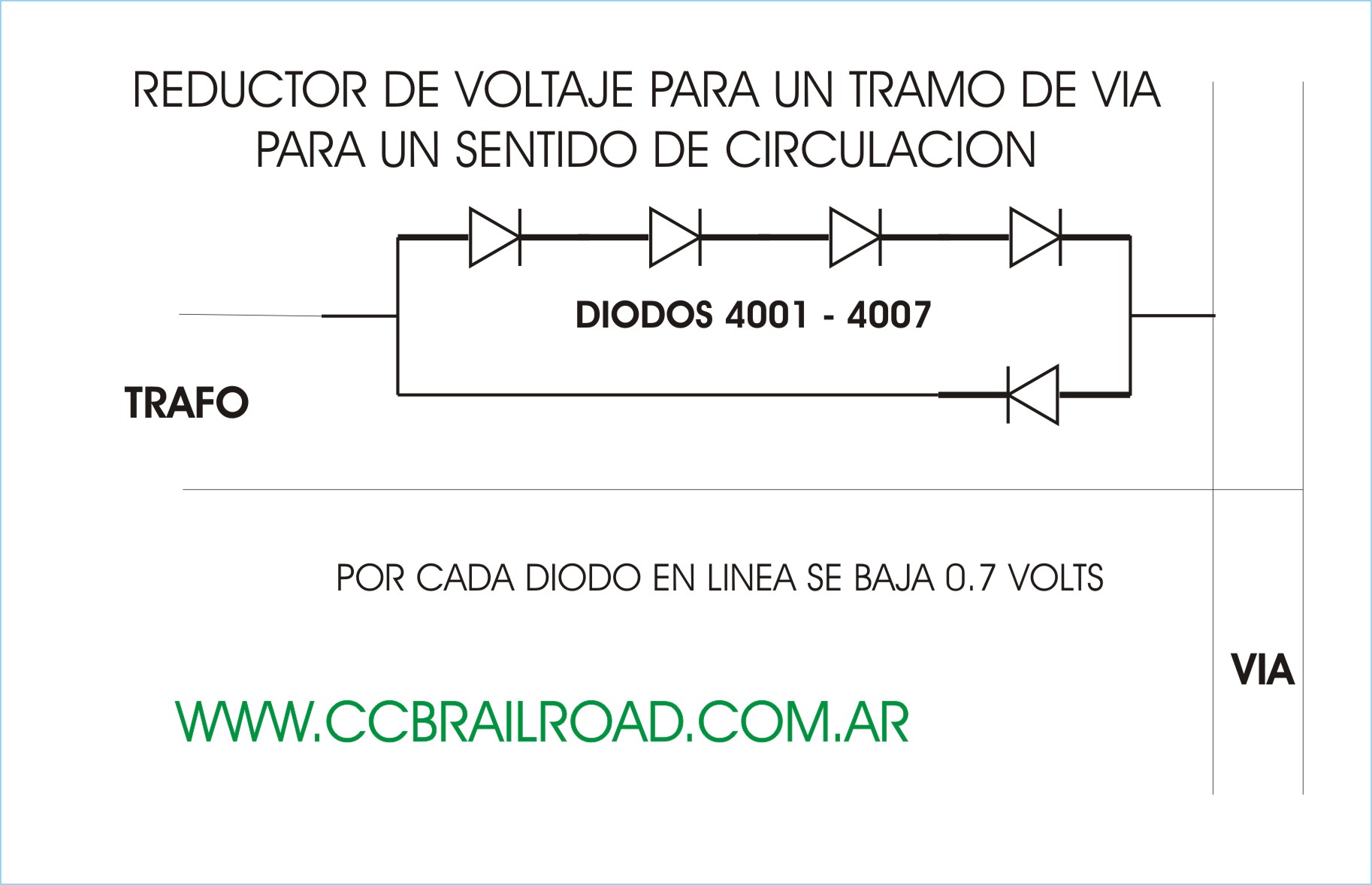
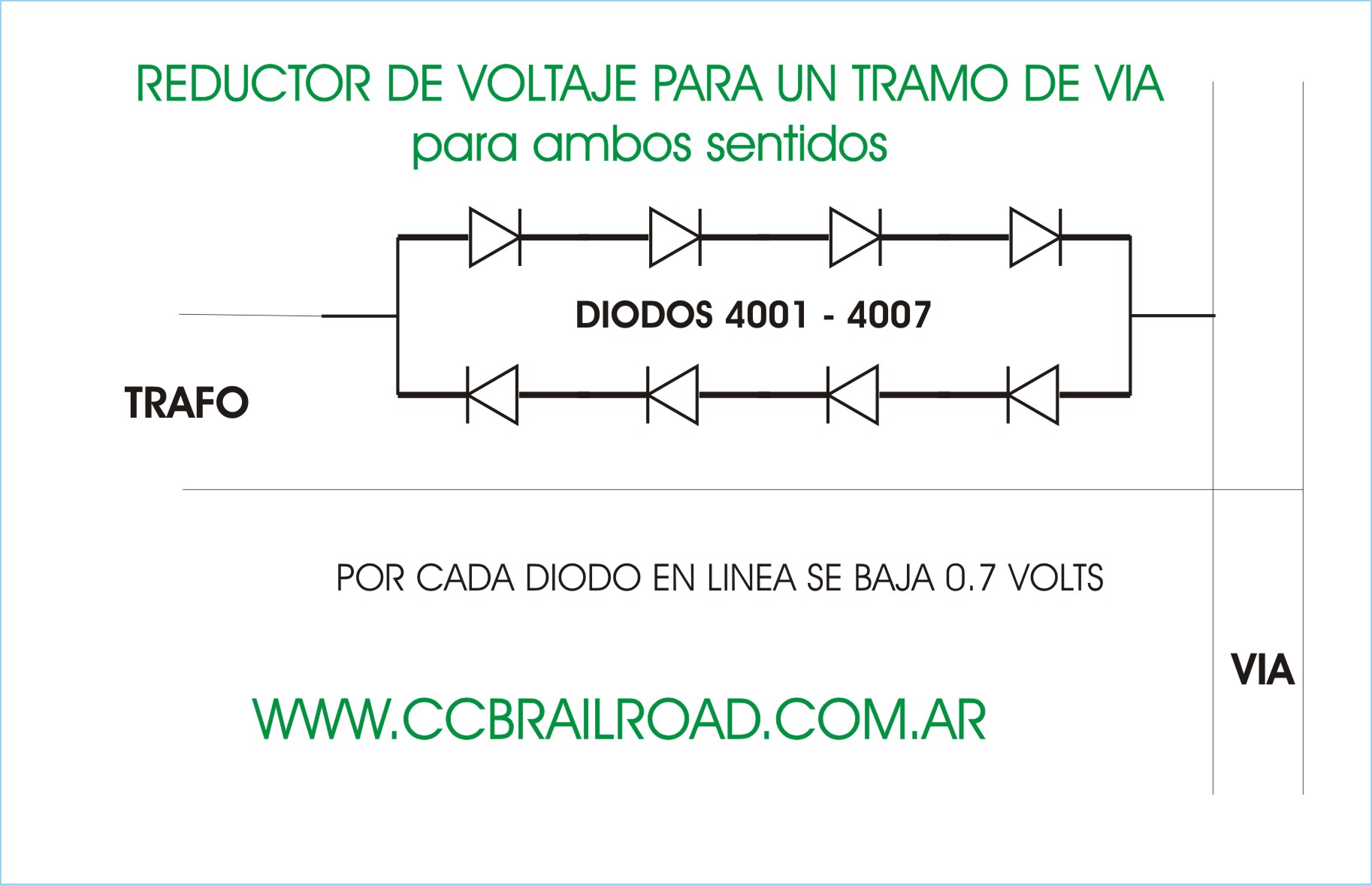
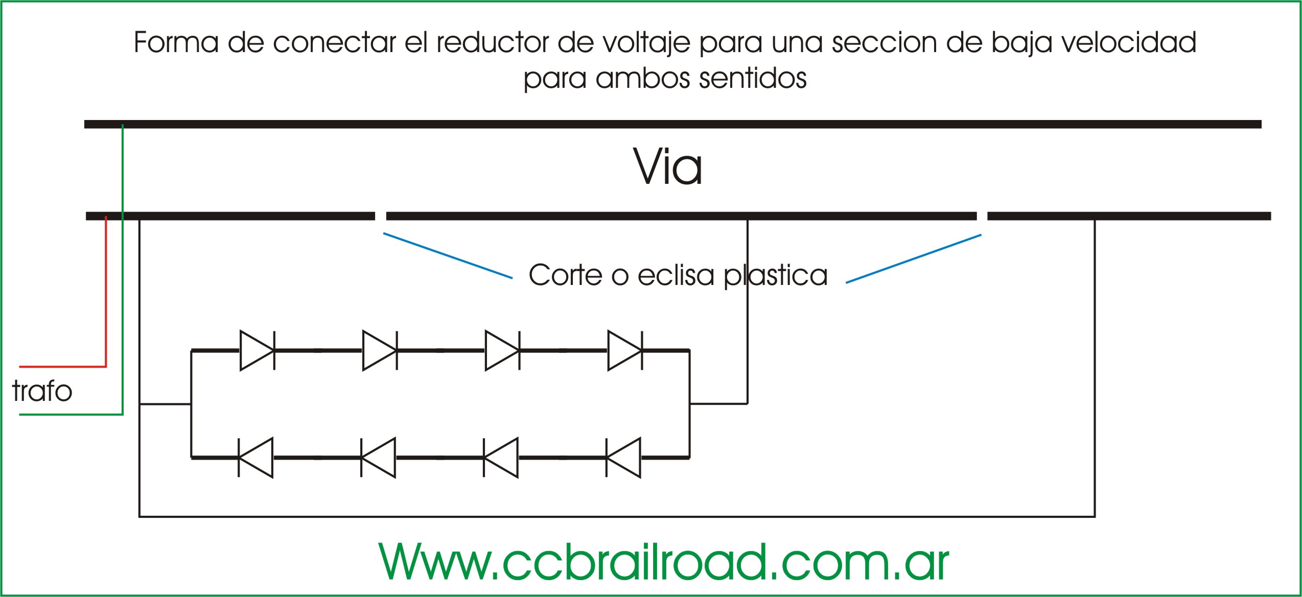
This diagram shows how reduce the voltage in a sector of via (insulated with plastic clips and powered by the circuit) that want less speed for each diode reduces 0.7V and can be used where necessary until you reach the voltage
suitable, this sector will have proportional voltage diodes used (12V power and 4 diodes are reducing to 9V approx., if we feed with 6V have 3V approx), any line 4001 to 4007.BR diodes
In the graph on the left reduces in a single direction of travel and the right in both directions.